
Dryer Outlet Wiring
Wiring a Dryer Receptacle & Circuit
Dryer wire cable between circuit panel and dryer plug is 10 AWG, black / red / white / bare (or green). X & Y are interchangeable, red and black wires are ungrounded (hot) wires, one wire on the X, and the other on the Y. The grounded conductor (neutral [white]) and the bare (or green) equipment ground wire MUST be on there designated connection. In the diagram bellow the bare (or green) ground is indicated by a green line. The bare (or green) wire should also be grounded to the electrical box (if metallic).
Be sure to use the properly rated electrical box designed to be used with a dryer receptacle.
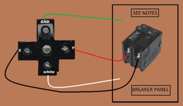
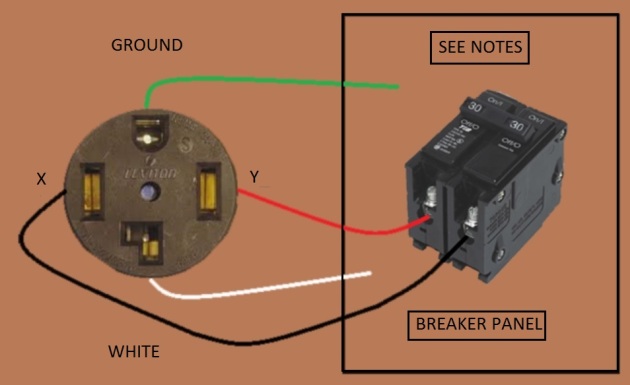
Ground = Equipment Grounding Conductor
X & Y = Interchangeable with the 2 Ungrounded Conductors (Hots)
White = Grounded Conductor (Neutral)
DRYER RECEPTACLE & CIRCUIT

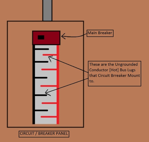
The breaker used must be a dual (double pole) 30 amp 220v breaker. 220v breaker meaning that the breaker must be of the type that actually connects to both ungrounded (hot) bus bars in the panel, every other bus lug in the panel is on the opposite phase of the incoming power line. refer to the picture below and to the left.
If you were to measure the voltage between a red lug and a black lug (they are not really those colors in the panel, just used here for explanation purposes) , you would measure between 220 to 240v, if you were to measure between a black bus lug and a ground or neutral bus, you would measure 110 to 120v, and the same would hold true if you measure between a red bus lug and the ground or neutral bus.
The equipment grounding bus is a terminal block with many small holes where the bare ground (or green wire) can be connected and tightened into place with a screw.
The grounded (neutral) bus is a terminal block also with many small holes where the white neutral wire can be connected and tightened into place with a screw.
A Safety Note about Breakers
A breaker designed to be used with 220v, is a dual (double pole) breaker that actually when mounted into the panel connects to both ungrounded conductors (hots) of the incoming power , in other words connects to both the red and black panel lugs (colors in illustration, your panel is not colored but will be alternating between phases from one lug to the next). Sometimes in some panels you may have a set of 4 breakers moulded together and they mount in the panel over the 2 lugs , the middle 2 breakers would be the two 30 amp breakers and the outer 2 could be 15 or 20 amp breakers for use in general purpose 110 v circuits. If you ask you local building or electrical supply depot for a dual 30 amp breaker for use in a 220v dryer circuit for this model/make breaker panel, they will be able to pick out the correct breaker for you. Please note, electrical panels are dangerous to work in, never touch any of the main ungrounded bus lugs in the panel, they can kill! A breaker can be installed without physically touching the ungrounded bus lugs. To be even safer you can switch the main breaker off to de-activate the panel while installing the breaker, use a second person to help with a flashlight if needed.
Also note that a 220 dual breaker has both breakers bridged so that if one of the dual breakers where to trip then both sides of the dual double pole breaker will shut down.
The equipment grounding wire connects to the equipment ground bus. Just look where all the other bare (and green) equipment grounding wires are going in the panel.
The grounded conductor – white (neutral) wire gets connected to the neutral bus. Just look where all the other white wires are going in your panel. Should be on its own connection screw hole within the neutral bus.
The red and black wires (ungrounded conductors [hot]) from dryer cable connect to the dual 30 amp breaker, one to each of the dual breakers.
Bellow is information on the older style 3 wire cords and the new 4 wire cords
Although most times on this website I use the electricians technical identification of wires but I have used the layman term bellow (so it is not as much of a tongue twister in the explanation) as follows…
HOT – ungrounded conductor
NEUTRAL – grounded conductor
GROUND – equipment grounding conductor
Dryer Cord – 3 wire hook-up at Dryer
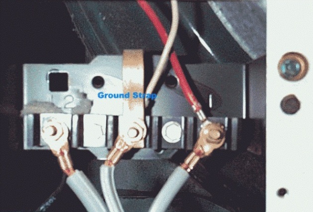
Photo used with permission from Jeff Worrall at Appliance Aid
3 wire dryer power systems are for use with existing ungrounded dryer receptacles mainly in older homes whose wiring in years gone by was not grounded.
This picture above shows a dryer cord (at the dryer end) with 3 wires only, No equipment ground wire. The center wire of this cable is the neutral wire and the outer wires are hot live wires. The hot wires connect to the outer 2 connections the power terminal block of the dryer, does not matter which is which as long as one hot is connected to each of the outer terminal connectors.
The center wire (neutral wire) of the cable goes to the center connector. Since in this case the neutral serves as a neutral and a ground connection, a jumper band (ground strap) is also connected to the center terminal and to the frame of the dryer. A green wire could also be used to connect the center connector to the frame of the dryer.
In the example in the picture the dryer doesn’t have color designation on the wires, follow direction above; if the dryer cord does have colored wires, white is the neutral wire to the center connector, the red and black wires are the hot live wires which connect to the 2 outer connections of the dryer terminal block, don’t forget the ground strap or green wire jumper from the center connector to the dryer frame.
Note: All new dryer circuit / receptacle installations must be grounded, which means you would be using a 4 wire dryer cord with a new circuit install.
Dryer Cord – 4 wire hook-up at Dryer
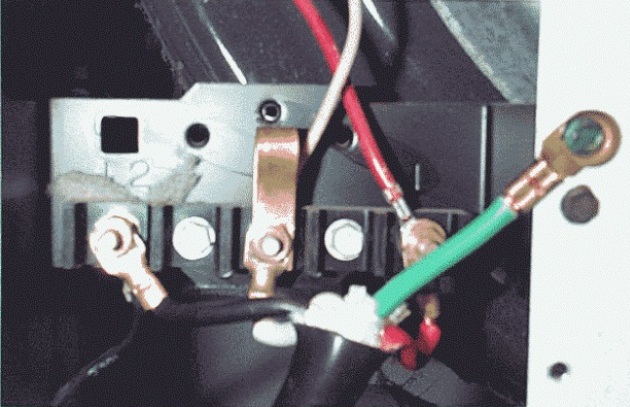
Photo used with permission from Jeff Worrall at Appliance Aid
A 4 wire dryer cord contains a black, red, white and green wire. The red and black wires are hot live wires and get connected to the 2 outer connectors on the dryers power terminal block, doesn’t matter which is which as long as it is the outer two connectors. The green wire is a ground wire and gets connected to the frame of the dryer. The white wire is a neutral wire and must be connected to the center connector on the dryer power block. No ground strap is used in a 4 wire setup (grounded circuit). In the sample picture above the ground strap in folded over and is connected to the center connector but NO connection from it or jump to ground. The ground strap could also be removed if you wish as it is not needed in this installation.
Additional notes
250-138 new branch circuits for ranges and dryers and 250-140 existing branch circuits for ranges and dryers.
Use a 30 amp 240 volt double pole breaker in the panel. Run a 10/3wGrnd Romex ®, cable. This cable should be rated as a 10 awg cable with a red, black, white, and bare conductor in that cable. At the panel connect the black and red wire to the 30 amp double pole breaker. Connect the white and bare wire to the neutral / ground bars in the panel.
Run the cable concealed in crawl or in attic or in walls.
At the dryer end use a 30 amp rated 4 prong dryer receptacle. The black connects to either the outside left connecting lug and the red connects to the other outside connecting lug. The white connects to the center connecting lug and the bare connects to the green connecting lug or screw. All these connections are inside that 30 rated 4 prong dryer receptacle.
The pigtail to your dryer will have to be changed to a 4 prong pigtail with the two outside cables connecting to the two outside screws found on the connecting block inside the dryer. The center white conductor is connected to the center screw of that dryer connecting block. the bare or green conductor connects to the metal frame of the dryer on a green screw provided.
The above is for a new branch circuit serving an existing or new dryer.
If you can move an existing three prong dryer to your new desired location then you may use this three prong receptacle still as existing only if the cable is an SE type cable with a red, black, and bare conductor. This bare conductor must wrap around the black and red wire as a protector within that SE cable. If you have a cable that is Romex ® but not with the identification of being an SE cable written on the side of that cable, or the bare wire does not wrap the black and red conductors, then you must upgrade that branch circuit to the new requirements using a four conductor cable and a four prong receptacle as described above at the beginning of this article.
If you are using a three prong receptacle as existing then the pigtail must be a three prong pigtail with the two outside wires of that pigtail connected to the two outside screws of the connecting block found in the dryer. The center conductor of the pigtail is connected to the center screw of that same connecting block inside the dryer. There must also be a green jumper wire installed between the center connection on that connecting block in the dryer and the metal frame of the dryer on a green screw.
WHILE EXTREME CARE HAS BEEN IMPLEMENTED IN THE PREPARATION OF THIS SELF-HELP DOCUMENT, THE AUTHOR AND/OR PROVIDERS OF THIS DOCUMENT ASSUMES NO RESPONSIBILITY FOR ERRORS OR OMISSIONS, NOR IS ANY LIABILITY ASSUMED FROM THE USE OF THE INFORMATION, CONTAINED IN THIS DOCUMENT, BY THE AUTHOR and / OR PROVIDER.
By: Donald Kerr