
Doorbell Systems
Hardwire Doorbell System
Doorbell Wiring is relatively simplistic compared to the rest of your home wiring, and works on a much lower “safer” voltage. Lower voltage also means that smaller wires can be used , 18 awg wire at either 2 or 3 wire cables (depending on your wiring choice). Like most things electrical , making it work means completing the circuit, without creating a dead short.
Doorbell power source:
small transformer , power by 120 v , with an output of much smaller voltage usually at 16 volts.
Doorbell buttons:
A convenient means of completing the circuit, located and mounted on the outside of an entrance to the home, may be used at one door or at 2 entrances. 2 wires are hooked to connectors of the button assembly, when the button is pushed , the contact is closed and thereby making an electrical connection between the 2 wires, and the connection is broken when the button is released.
Doorbell Ringer/Chime:
The sounding device that produces a ring, or chime or other type of sound when someone pushes the doorbell button. Some have a different ring/chime pattern depending on if the front or back door button is pushed.
Methods of Wiring
Please Note, that for very long runs of wire, you may need to increase from a 16 volt transformer to a 24 volt transformer to compensate for the voltage drop if experienced. In cases where 2 chimes (2 separate sounding units) are used (located in different parts of the house) and run off the same buttons/transformer, may also need to increase from a 16 volt transformer to a 24 volt transformer. A diagram showing how to add a second sounding unit is located after the 3 wiring option diagrams.
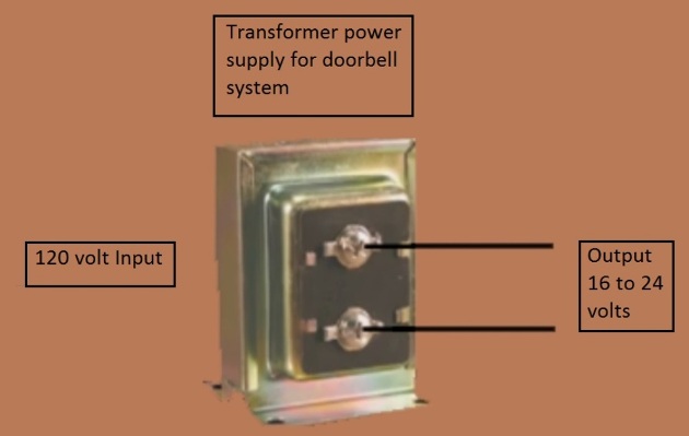
The 120v side of the transformer gets connected to a circuit that leads to the electrical panel.
The 16 to 24 volt side of the transformer is what is actually feeding the wires of the doorbell circuit.
NEVER CONNECT THE 120 VOLT SIDE TO THE DOORBELL SYSTEM CIRCUIT !
Always read your documentation that comes with the sounding unit (chimes) for voltage requirements, these requirements for specific voltage may need to be increased for very long runs of wire to compensate for voltage drop or for use in multiple sounding devices on the same doorbell system.
- Power source going directly to sounding device (ringer/chime), button wiring coming individually from each button to ringer/chime.
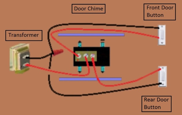
Always read the instructions that came with the doorbell chime as the connections may be differently configured on the unit you buy than in the illustration above.
One wire from the transformer goes to the common connection screw of the sounding device, the other wire from the transformer gets connected to one wire going to front door button and one wire going to rear door button.
The other wire from front door button goes to one of the remaining connection screw at sounding device, and the other wire from rear door button goes to the last remaining screw of sounding device.
Note you may want the front door to make a ding-dong at the sounding device and the back door to make just a ding at the sounding device. If these sounds are reversed then just switch the wire on screws coming back from the buttons (in the drawing that would be the left most and right most connection screw). The black and red wires in the diagram are for illustration purposes, your wires may be a different color.
**********
2. Power source going directly to sounding device (ringer/chime), button are looped from one button to the next on a single cable and all button wires go to the chime on the same cable.
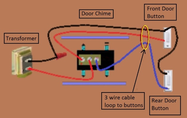
Always read the instructions that came with the doorbell chime as the connections may be differently configured on the unit you buy than in the illustration above.
The black blue and red wires in the diagram are for illustration purposes, your wires may be a different color.
One wire from the transformer goes to the common screw of the sounding device. The other wire from the transformer gets connected to one wire going to the buttons. That wire gets connected to one screw on each of the doorbell buttons.
This method uses a 3 wire cable going from the sounding device to the buttons. Of the remaining 2 wires in the cable going from the sounding device to the buttons…At the sounding device , one wire goes to connection screw (far left connection on chime drawing) and the other wire goes to the other connection screw (far right connection of chime in drawing).
At the buttons, one of the remaining wires gets connected to the remaining screw of front door button and the other wire gets connected to the remaining screw on rear door button.
Note you may want the front door to make a ding-dong at the sounding device and the back door to make just a ding at the sounding device. If these sounds are reversed then just switch the wire on screws coming back from the buttons (in the drawing that would be the left most and right most connection screw).
*********
3. Power source gets looped to the door buttons and onward to the doorbell sounding device (ringer/chime) all wires power and button feeds arriving at the sounding device in the same cable.
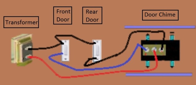
Always read the instructions that came with the doorbell chime as the connections may be differently configured on the unit you buy than in the illustration above.
The black blue / blue and red wires in the diagram are for illustration purposes, your wires may be a different color.
One wire from the transformer is connected to one connection screw of each doorbell button. The other transformer wire continues on until it gets to the sounding device where it gets connected to the common screw.
A 3 wire cable is used, and of the remaining 2 wires – one wire gets connected to the remaining screw of the front door button. The last remaining wire gets connected to the remaining screw on the rear door button.
At the sounding device the remaining 2 wires gets connected to the remaining connection screws at chime, 1 wire on each screw.
Note you may want the front door to make a ding-dong at the sounding device and the back door to make just a ding at the sounding device. If these sounds are reversed then just switch the wire on screws coming back from the buttons (in the drawing that would be the left most and right most connection screw).
**********
Using 2 Sounding Units (chimes)
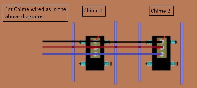
The black blue / blue and red wires in the diagram are for illustration purposes, your wires may be a different color.
To hook up a second sounding unit..
Connect a 3 wire cable from unit one to unit 2,
Screw 1 wire from unit one goes to screw 1 of unit two.
Common screw on unit one to common screw of unit 2.
Screw two on unit one to screw 2 of unit 2.
Please Note that in some cases you may need to replace the transformer feeding power for the doorbell system from 16 volts to up to 24 volts to handle the extra load of a second doorbell sounding device.
*********
Using 2 buttons on the rear or 2 buttons on the front
Option 1:
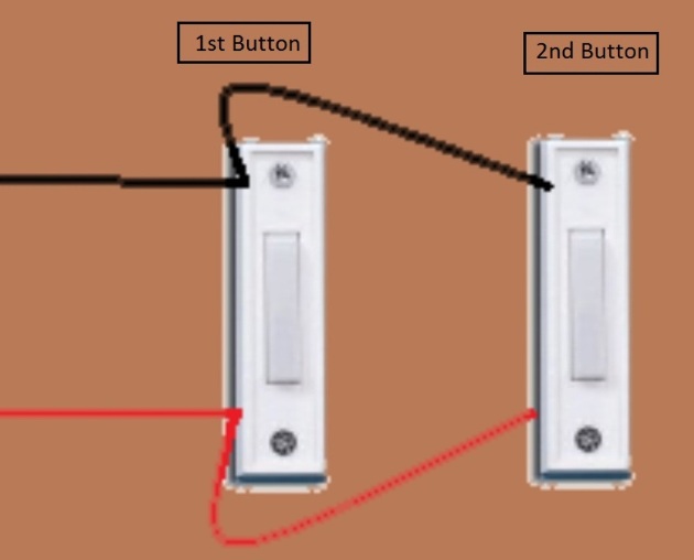
The black blue and red wires in the diagram are for illustration purposes, your wires may be a different color.
To add additional doorbell buttons, you may add an additional button on either the front door button or the back door button. In the wiring options above 2 wires are connected to each door button,
To extend to another front button (or another rear button) connect another 2 wire cable to run from the 1st button to the 2nd button. Then connect one wire to each of the 2 screws (these 2 screws already have a wire on them as per the above diagrams, you are now adding a 2nd wire to on each screw to extend to the next button) at the add on button connect the 2 wires , one wire on each connection screw.
Option 2: (only if your doorbell system wiring has both wires of the transformer coming to the sounding unit first)
- A new 2 wire cable is run from the sounding (chime) unit to the add on button.
- At the sounding (chime) unit connect one wire of the cable to either screw 1 or 2 (depending if you want the new button to produce a ding-dong or just a ding. The other wire connects to the transformer wire that is NOT connected to the common screw of the sounding unit.
- The other end of the cable at the new button , one wire gets connection to each of the connection screws.
WHILE EXTREME CARE HAS BEEN IMPLEMENTED IN THE PREPARATION OF THIS SELF-HELP DOCUMENT, THE AUTHOR AND/OR PROVIDERS OF THIS DOCUMENT ASSUMES NO RESPONSIBILITY FOR ERRORS OR OMISSIONS, NOR IS ANY LIABILITY ASSUMED FROM THE USE OF THE INFORMATION, CONTAINED IN THIS DOCUMENT, BY THE AUTHOR and / OR PROVIDER.
By: Donald Kerr