4 Way Switch Circuits
Adding Additional 4 way switches

At the beginning and end of a 4 way switch circuit must be a 3 way switch, in between these two 3 way switches you can install an unlimited number of 4 way light switches.
Certain rules you must follow…
At the 3 way switches located at the start and end of the switch circuit,…
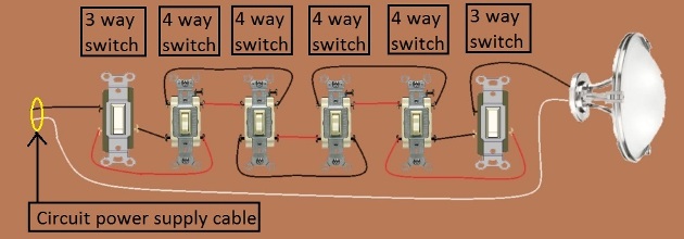
- a) one 3 way switch must have the ungrounded conductor (hot) from the ‘circuit power supply cable’ connected to the common screw of the 3 way switch.
b) the other 3 way switch must have the switched ungrounded conductor (hot) from the fixture connected to the common screw of that 3 way switch.
c) two other wires run between the switches (they are referred to as the traveler wires).
For the 4 way switches that lie between the 3 way switches….
There are two sets of connectors (I will refer to them as matching pairs of screws) the two traveler wires coming from a previous switch must go to the two screws of the 4 way switch that is a matching pair. The other matching pair of screws connect the two traveler wires to the next switch. Now you can continue that sequence for as many 4 way switches as you wish to use, but the last switch (as well as the first) in the circuit will be a 3 way switch.
The type of wire cable you use to go between the switches is a 3 wire plus bare, usually a red, black, white and bare wire. Two of the wires are used as traveler wires, and the 3rd one to carry a wire connected between the 1st and the last switch, what the 3rd wire does depends on the configuration used. In the example in the diagram above the 3rd wire is the grounded conductor (neutral) that is being routed to the last switch which feeds the fixture itself.
In the example in the picture above there are 6 switches there, a 3 way switch at the beginning and end, and four 4-way switches in the middle. By following the same pattern more 4 way switches could be added in the middle, or some removed.
Be aware that there are a variety of manufacturers that make switches, so always pay attention to what screws on a 4 way switch are matching pairs, and where the common screw is on a 3 way switch, as it is possible that the switch you buy may have the screws in a different configuration / layout / location that what is depicted in the illustrations I provided.
Foreign Users:
The colors of the wires depicted are based on the standards and code requirements / configuration in the United States and Canada. If you are viewing this site from a foreign country, your wiring standards and color of wires may be different but the principal and sequence of wiring will still remain the same. Therefore the information in this article may still be of use to you regardless of what country you may be in. Just translate the colors used here to the color of wires used in your country in regards to ungrounded (hot) conductors / grounded conductors (neutral) and equipment grounding conductors as well know applicable code requirements in your country.
WHILE EXTREME CARE HAS BEEN IMPLEMENTED IN THE PREPARATION OF THIS SELF-HELP DOCUMENT, THE AUTHOR AND/OR PROVIDERS OF THIS DOCUMENT ASSUMES NO RESPONSIBILITY FOR ERRORS OR OMISSIONS, NOR IS ANY LIABILITY ASSUMED FROM THE USE OF THE INFORMATION, CONTAINED IN THIS DOCUMENT, BY THE AUTHOR and / OR PROVIDER.
By: Donald Kerr