Outlet, Half Switched Circuit Wiring
2011 NEC Compliant
Power Source at Outlet controlled by 3 way switches
For those that live where the new 2011 NEC code is in effect, please read
‘2011 NEC New Rule ‘Switch Connections’
If this applies to you, the switch wiring options that is in compliance with this new rule will be indicated bellow as ‘2011 NEC compliant’
2011 NEC Compliant Circuit
You will need…
- A 3 wire cable that is routed between the switch box 1 and the outlet box – this wire cable comes with a black / red / white wire plus the bare equipment grounding wire.
- A 4 wire cable that is routed between switch box 1 and switch box 2 – these wire cables comes with a black / red / blue (or white striped) / white wire plus the bare equipment grounding wire.
- A circuit power supply source wire cable that is routed to outlet.
- Insulated wire nuts to connect / join wire together, variety of sizes out there so make sure you obtain the correct size.
- Wire staples, to affix the wire cables to wall studs as needed. Wire cable must be secured within 6 inches of entering the electrical box.
- Wire cable / wire strippers, and pincher pliers that can break off the joining tab on outlet (read connection instructions bellow).
- Screwdrivers as required.
Holes drilled to feed wires through studs must be 1 1/4″ from edge of stud, in instances where the wire cable is closer then the edge of stud must have a 1/16-in. thick protective metal plate over the area where the cable is being feed through (may want to notch the stud so that that the protective plate does not create a bump on the drywall). Also read the article called ‘Wire Routing Basics’
Wire cables entering the electrical box – secure the cable clamp at the box snug enough that the cable cannot come out but not too tight as to pinch the cable and break through the insulated cover of the cable.
You must have at least 6 inch length of wire inside the electrical box, it can be a bit more but not less, it can fail an inspection if the length of each wire is less than 6 inches. Also read the article called ‘Box Fill Calculations’ as there is a limit on how many wires are allowed for a certain size electrical box.
STEP 1 – Make certain that the power supply cable is dead – turn off the electrical breaker at the service panel. Make certain that everyone in the house is aware of what you are doing so that they do not get the notion to reset the breaker when another light in the home is not working.
STEP 2 – Make the box openings (if a existing home)
STEP 3 – Feed / Route the wire cables.
STEP 4 -Mount / Install the Electrical Boxes which should be flush with the finished wall, not beyond so that the wall plate will also be flush; then feed the wire cables into the electrical boxes. Sometimes because of tight openings in existing homes, the wire cable may to be feed into the electrical box then the box put in position and secured.
STEP 5 – Connect the wires…
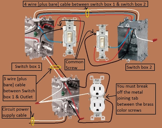
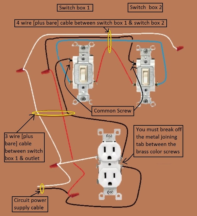
Connections Instructions:
(as depicted in the diagrams above)
At the Outlet box…
Two cables entering this box – one coming from switch, and one coming from ‘circuit power supply cable’
FIRST – break off the metal joining tab between the two brass color screws, DO NOT break off the metal joining tab between the silver color screws.
- a) using an insulated wire nut connect / join the white wire coming from switch 1 + the white wire coming from the ‘circuit power supply’ cable + the white wire connected to one of the silver color screws of outlet (this is the grounded conductor [neutral])
- b) connect the black wire coming from switch 1 to one of the brass color screws – this will be the switched half of the duplex outlet.
- c) using an insulated wire nut connect / join the black wire from the ‘circuit power supply’ cable + the red wire coming from switch 1 + the black wire connected to one of the brass color screws – this will be the ‘always on’ half of the duplex outlet.
- d) please see under important notes in regards to the equipment grounding conductor (bare wire).
At the Switch 1 box…
Two cables entering this box – one coming from outlet, one coming from from switch 2.
- a) connect the black wire coming from outlet to the common screw of switch 1.
- b) using an insulated wire nut connect / join the black wire coming from switch 2 + the red wire coming from outlet.
- c) using an insulated wire nut connect / join the white wire coming from switch 2 + the white wire coming from outlet.
- d) connect the blue wire from switch 2 to one of the remaining main screws of switch 1.
- e) connect the red wire from switch 2 to the last remaining main screw of switch 1.
- f) please see under important notes in regards to the equipment grounding conductor (bare wire).
At the Switch 2 box…
One cable entering this box coming from switch 1.
- a) connect the black wire coming from outlet to the common screw of switch 2.
- b) connect the blue wire to one of the remaining main screws of switch 2.
- c) connect the red wire to the last remaining main screws of switch 2.
- d) using an insulated wire nut cap off the white wire.
- e) please see under important notes in regards to the equipment grounding conductor (bare wire).
Important Notes:
By electrical codes you MUST have at least 6 inches of wire in the electrical box itself, and also the wire must be able to reach at least 3 inches outside the box, it can fail an electrical inspection if the required min. wire length is not met. You may have the wires a bit longer (within reason) but they cannot be shorter. Also see the note on box fill further down in this article.
What is not shown in the drawings to avoid confusion, is that each wire cable also has a bare equipment grounding wire included. This wire is connected to a grounding screw in each electrical box (if the box is metal), joined either through the grounding screws in the box itself or via a wire nut to the bare wire of the next cable entering / exiting the box, it is also connected to any grounding screw (if there is one) on the switch itself, as well as the equipment grounding screw of outlet (possibly a green screw). Now if using a plastic box, it is made of a material that is non conductive, however some plastic boxes have a metal strip inside that can still be used to connect equipment grounding wires, in the event that it does not use wire nuts to join the bare grounding wires together. The equipment grounding wire (bare in most cables) must be electrical conductively joined throughout the circuit. Green wires are also equipment grounding conductors.
Extensions to this Switch circuit…
Be Aware that there is a limit by code on how many wires can be in a given size electrical box, when adding more wires to the same box you may have to install a larger and / or deeper box to allow space for more wires coming and out of the box.
Here is an article / explanation in regards to box fill calculations ‘Box Fill Calculation’
The instructions here are based on the fact that the circuit has already been wired to the configuration shown in this article and we are now making the wiring changes for onward power.
From the Outlet location….
Both onward ‘always on’ and ‘switched’ power is available from the outlet location.
Option 1 – Onward Always on power..
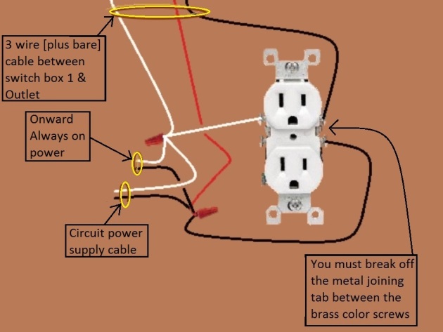
Not shown in the diagram but the onward cable also has a bare wire (equipment grounding conductor) that also must be connected to all the other bare wires at the outlet electrical box.
Connection Instructions for onward cable (always on)
- a) Using an insulated wire nut, attach / join – the white wire of onward cable + the white wire connected to the silver color screw of outlet + the white wire coming from the ‘circuit power supply cable’ + the white wire coming from switch 1.
- b) Using an insulated wire nut, attach / join – the black wire of onward cable + the red wire coming from switch 1 + the black wire coming from the ‘circuit power supply cable’ + the black wire connected to one of the brass color screws of outlet.
Identification of wires on onward cable….
Black – Ungrounded conductor (hot – always on)
White – grounded conductor (neutral)
Option 2 – Onward Switched power..
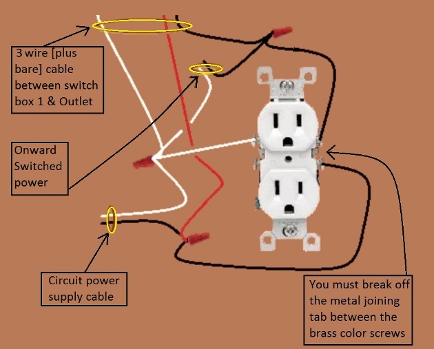
Not shown in the diagram but the onward cable also has a bare wire (equipment grounding conductor) that also must be connected to all the other bare wires at the outlet electrical box.
Connection Instructions for onward cable (switched)
- a) Using an insulated wire nut, attach / join – the white wire of onward cable + the white wire connected to the silver color screw of outlet + the white wire coming from the ‘circuit power supply cable’ + the white wire coming from switch 1.
- b) Using an insulated wire nut, attach / join – the black wire of onward cable + the black wire coming from switch 1 + the black wire connected to one of the brass color screws of outlet.
Identification of wires on onward cable….
Black – Switched ungrounded conductor (hot – switched)
White – grounded conductor (neutral)
Option 3 – Onward ‘Always on’ & Switched power..
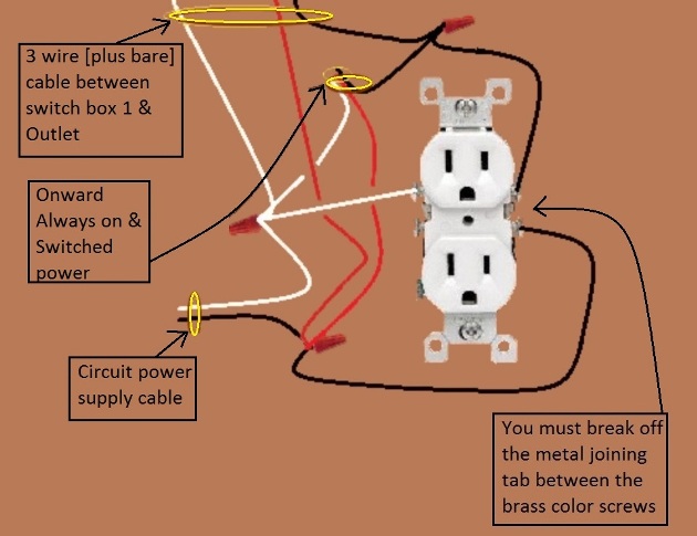
Not shown in the diagram but the onward cable also has a bare wire (equipment grounding conductor) that also must be connected to all the other bare wires at the outlet electrical box.
Connection Instructions for onward cable (‘always on’ & switched)
- a) Using an insulated wire nut, attach / join – the white wire of onward cable + the white wire connected to the silver color screw of outlet + the white wire coming from the ‘circuit power supply cable’ + the white wire coming from switch 1.
- b) Using an insulated wire nut, attach / join – the black wire of onward cable + the black wire coming from switch 1 + the black wire connected to one of the brass color screws of outlet.
- c) Using an insulated wire nut, attach / join – the red wire of onward cable + the red wire coming from switch 1 + the black wire connected to one of the brass color screws of outlet + the black wire coming from the ‘circuit power supply’ cable.
Identification of wires on onward cable….
Black – Switched ungrounded conductor (hot – switched)
Red – Ungrounded conductor (hot – always on)
White – grounded conductor (neutral)
From the Switch 1 location….
Both onward ‘always on’ and ‘switched’ power is available from the switch 1 location.
Option 1 – Onward Always on power..
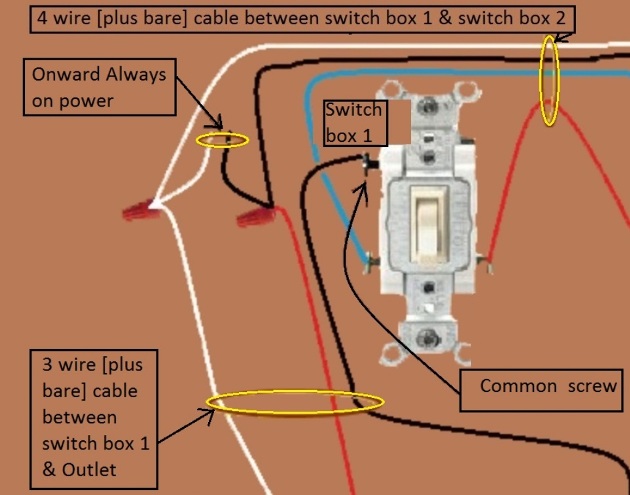
Not shown in the diagram but the onward cable also has a bare wire (equipment grounding conductor) that also must be connected to all the other bare wires at the switch electrical box.
Connection Instructions for onward cable (always on)
- a) Using an insulated wire nut, attach / join – the white wire of onward cable + the white wire coming from outlet + the white wire coming from switch 2.
- b) Using an insulated wire nut, attach / join – the black wire of onward cable + the red wire coming from outlet + the black wire coming from switch 2.
Identification of wires on onward cable….
Black – Ungrounded conductor (hot – always on)
White – grounded conductor (neutral)
Option 2 – Onward Switched power…
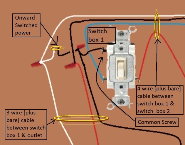
Not shown in the diagram but the onward cable also has a bare wire (equipment grounding conductor) that also must be connected to all the other bare wires at the switch electrical box.
Connection Instructions for onward cable (switched)
- a) Using an insulated wire nut, attach / join – the white wire of onward cable + the white wire coming from outlet + the white wire coming from switch 2.
- b) Using an insulated wire nut, attach / join – the black wire of onward cable + the black wire connected to the common screw of switch 1 + the black wire coming from outlet.
Identification of wires on onward cable….
Black – Switched ungrounded conductor (hot – switched)
White – grounded conductor (neutral)
Option 3 – Onward ‘Always on’ & Switched power..
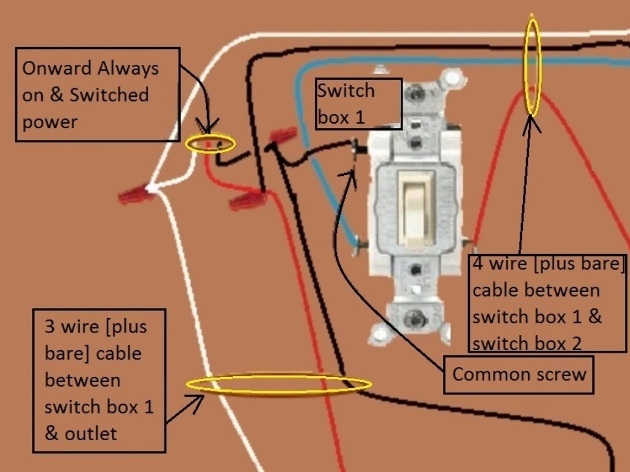
Not shown in the diagram but the onward cable also has a bare wire (equipment grounding conductor) that also must be connected to all the other bare wires at the switch electrical box.
Connection Instructions for onward cable (‘always on’ & switched)
- a) Using an insulated wire nut, attach / join – the white wire of onward cable + the white wire coming from outlet + the white wire coming from switch 2.
- b) Using an insulated wire nut, attach / join – the black wire of onward cable + the black wire connected to the common screw of switch 1 + the black wire coming from outlet.
- c) Using an insulated wire nut, attach / join – the red wire of onward cable + the red wire coming from outlet + the black wire coming from switch 2.
Identification of wires on onward cable….
Black – Switched ungrounded conductor (hot – switched)
Red – Ungrounded conductor (hot – always on)
White – grounded conductor (neutral)
From the Switch 2 location….
Only onward ‘always on’ power is available from the switch 2 location.
Option 1 – Onward Always on power..
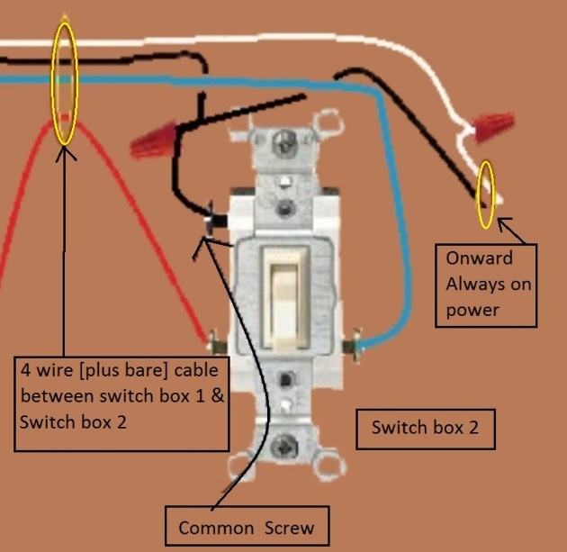
Not shown in the diagram but the onward cable also has a bare wire (equipment grounding conductor) that also must be connected to all the other bare wires at the switch 2 electrical box.
Connection Instructions for onward cable (always on)
- a) Using an insulated wire nut, attach / join – the white wire of onward cable + the white wire coming from switch 1.
- b) Using an insulated wire nut, attach / join – the black wire of onward cable + the black wire coming from switch 1 + the black wire connected to the common screw of switch 2.
Identification of wires on onward cable….
Black – Ungrounded conductor (hot – always on)
White – grounded conductor (neutral)
Foreign Users:
The colors of the wires depicted are based on the standards and code requirements / configuration in the United States and Canada. If you are viewing this site from a foreign country, your wiring standards and color of wires may be different but the principal and sequence of wiring will still remain the same. Therefore the information in this article may still be of use to you regardless of what country you may be in. Just translate the colors used here to the color of wires used in your country in regards to ungrounded (hot) conductors / grounded conductors (neutral) and equipment grounding conductors as well know applicable code requirements in your country.
WHILE EXTREME CARE HAS BEEN IMPLEMENTED IN THE PREPARATION OF THIS SELF-HELP DOCUMENT, THE AUTHOR AND/OR PROVIDERS OF THIS DOCUMENT ASSUMES NO RESPONSIBILITY FOR ERRORS OR OMISSIONS, NOR IS ANY LIABILITY ASSUMED FROM THE USE OF THE INFORMATION, CONTAINED IN THIS DOCUMENT, BY THE AUTHOR and / OR PROVIDER.
By: Donald Kerr
